Bought ECG-HVM6.5KP-48V hybrid solar inverter with integrated WiFi. Mention is to use this for battery bank testing. Inverter has USB look-like port but there is nothing to do with USB with it.
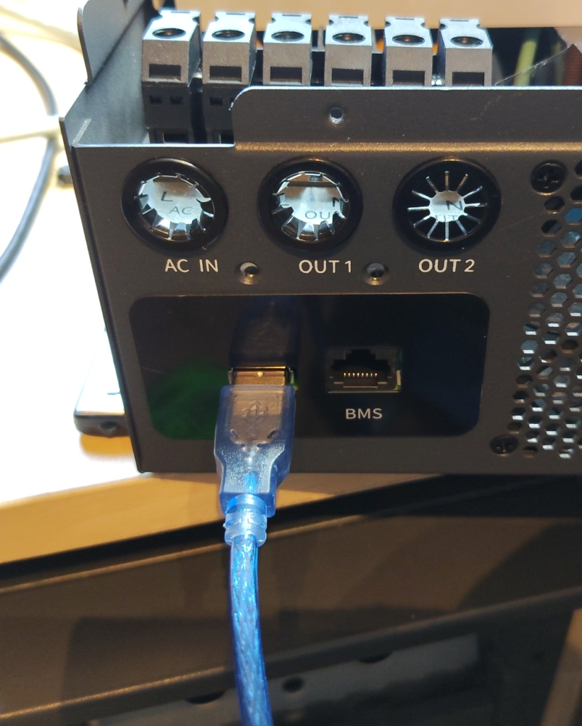
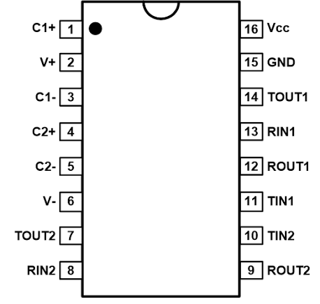
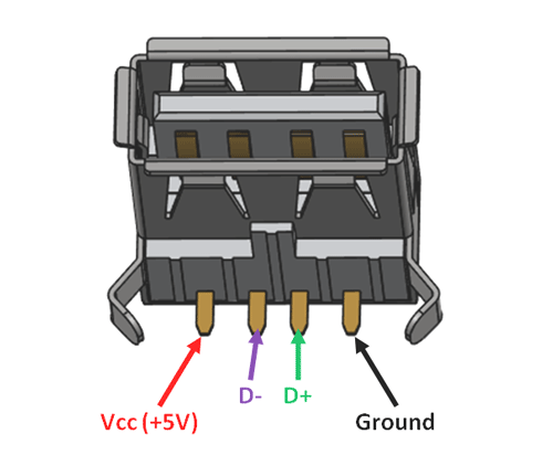
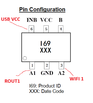
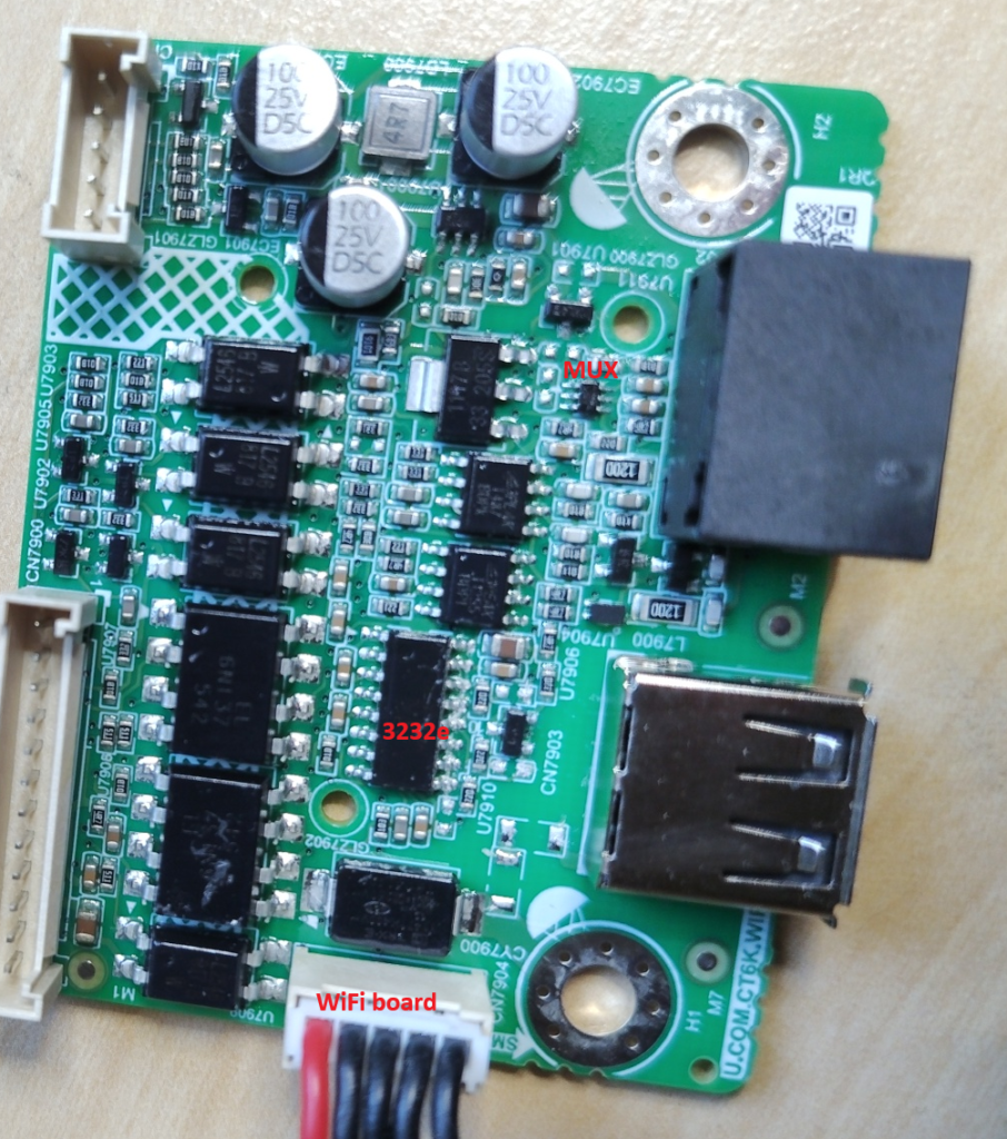
There is 3peak 3232e TLL to RS232 transceiver IC directly connected to USB port pins. USB port D+ pin is connected to 3232e TOUT1 and D- to RIN1. So, We need to build special ”USB to RS232” cable by just soldering DB9 Connector to cut USB A cable tail.
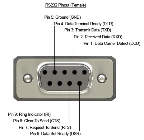
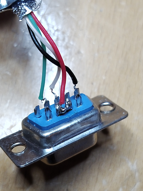
DB9 PIN2 (RX) –> Green –> USB D+
DB9 PIN3 (TX) –> White –> USB D-
DB9 PIN5 (GND) –> Black –> USB Ground
But this is not the full story! You can get Modus replies to WiFi module visible with this connection but you cannot request anything by yourself! 3232e TIN1 pin is directly shared with WiFi RX pin but ROUT1 is muxed with SOT23-6 BL1551B SPDT analog switch. There is very interesting control for the mux. It is controlled with USB VCC signal!
There is also resistors and protecting diodes connected to that USB VCC line. So, line can be directly controlled with RS232 control pins. I connected that to DTR. This line should be also set automatically high when port is opened and back to low when closed as standard procedure. Sending and receiving data should be transparent operation for example from Linux command line and not needing any extra set or clear pin state commands. So, missing connection:
DB9 PIN4 (DTR) –> RED –> USB VCC
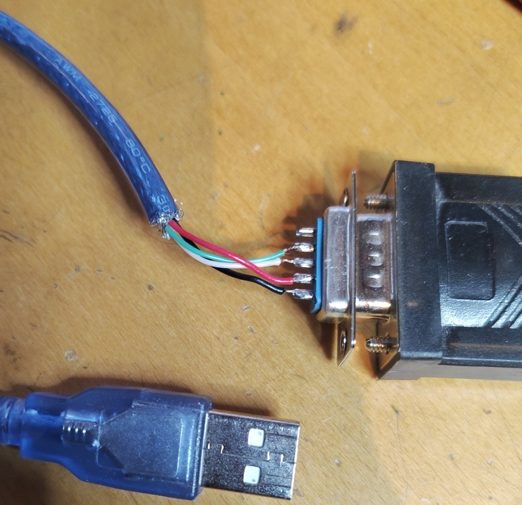
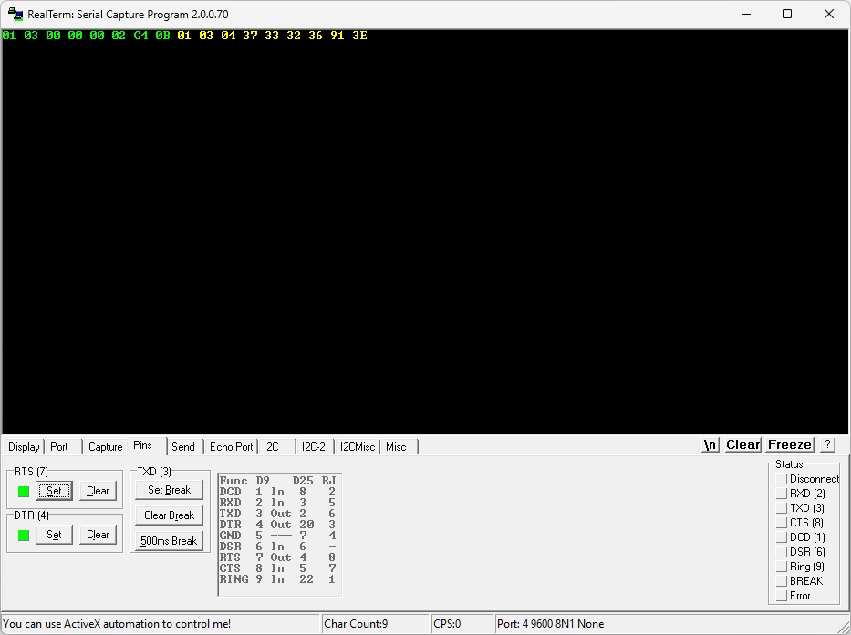
Finally we can connect DB9 connector to ”real” serial to USB converter and plug that USB side to PC (Raspberry Pi or anything). After that all we can write Modbus requests to serial port with settings 9600bps 8n1, standard modbus RTU and DTR enabled:
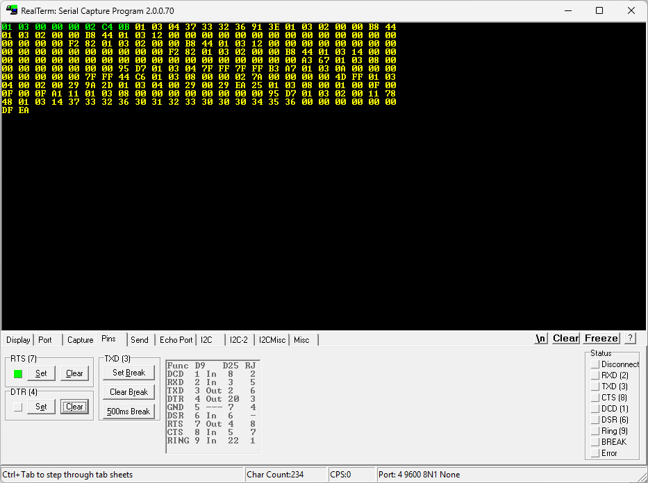
And we can see normal WiFi messages started rolling when DTR is cleared:
Linux Shell Integration
My need to control inverter registers is very much limited for timed output source priority setting. This is done directly from my Linux server. There is not any actual home automation SW running, so, I let this home automation integration for other people.
It turned out that driving DTR from shell script while sending data is little bit complicated. stty setup comand is instead supporting RTS/CTS HW handshaking. So, modified connection little bit for that:
Moved USB cable red line to RTS and soldered also CTS together.
DB9 PIN7+8 (RTS+CTS) –> RED –> USB VCC
Modbus register map was found from here: https://github.com/GamesterUnknown/ESPHome_JSDSolar_inverter/tree/main/docs
Output source priority register is at address 0x4102 and values for that: 0:GPB 1:PGB 2:PBG 3:MKS
Following script puts inverter to Grid first mode:
#!/bin/bash
stty -F /dev/ttyUSB0 speed 9600 cs8 crtscts -cstopb -parenb -echo
echo -en '\x01\x10\x41\x02\x00\x01\x02\x00\x00\xF6\xB6' > /dev/ttyUSB0
And this to PBG priority mode:
#!/bin/bash
stty -F /dev/ttyUSB0 speed 9600 cs8 crtscts -cstopb -parenb -echo
echo -en '\x01\x10\x41\x02\x00\x01\x02\x00\x02\x77\x77' > /dev/ttyUSB0
These scripts can be then timed with Cron.
Backround for changing priority
Intention for this is solar panel setup is:
Daytime:
* Charge batteries
* Feed power to load
* Sell excess energy to grid
After sunset:
* Use batteries to power load
* Use grid when batteries are empty
It turned out that inverter is pushing excess energy to grid only in ’Grid first’ mode. In all other modes it is just limiting panel input power when batteries are full. So, there is not choises for daytime mode. But there is no sense with this mode during night time as grid is priorized and it is then never using batteries! Timed mode change gives also possiblity to optimize time for changing on batteries and using their energy.