Hardware
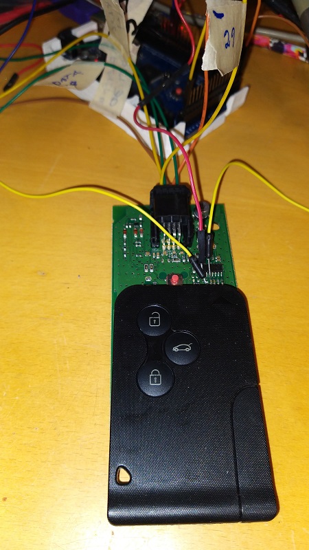
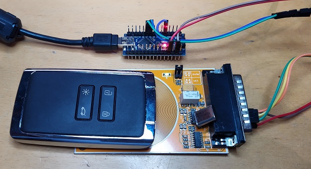
It is needed some 125kHz RFID reader to be able to communicate with Hitag key tags. In this project we use old Renault car card reader that is fairly well (cheap) available in scrapyards and uses PCF7991 base station IC that has also well documented datasheet available.
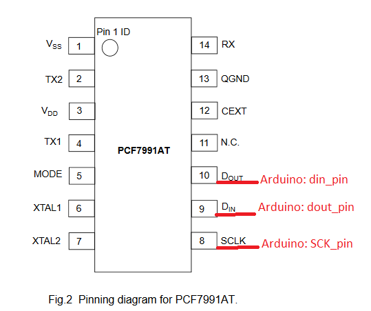
din_pin = 21;
dout_pin = 7;
SCK_pin = 6;
Source codes available at GitHub: https://github.com/kivijakola/hitager/tree/main/Arduino
Now also tested to be compatible with Arduino Nano! Use for example following pin settings:
const int SCK_pin = 6;
const int dout_pin = 7;
const int din_pin = 2;
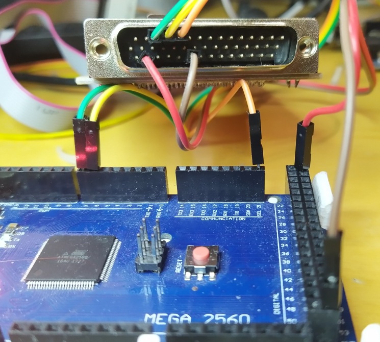
No other changes required. din_pin must have external interrupt feature on it! Arduino Mega2560 is also compatible with din_pin = 2
New Tag Reader HW version
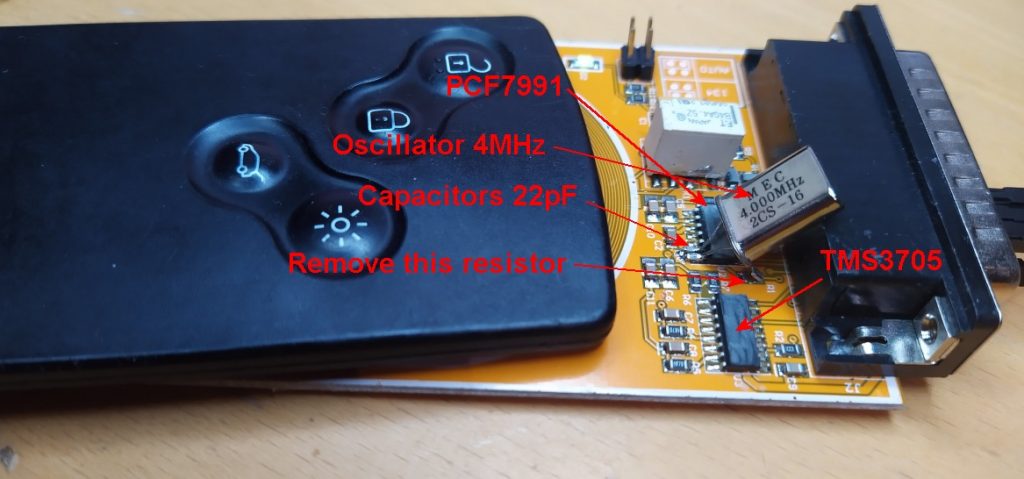
I decided to ordered cheap Chinese RFID adapter for IPROG (~12USD) from Aliexpress: https://www.aliexpress.com/af/-RFID-adapter-for-IPROG.html Don’t buy full set! Only the adapter! This board has direct interface to PCF7991 via connector. There is also TMS3705 IC on board that may be used for programming tags using FSK modulation. (PCF7991 handles ASK modulation)
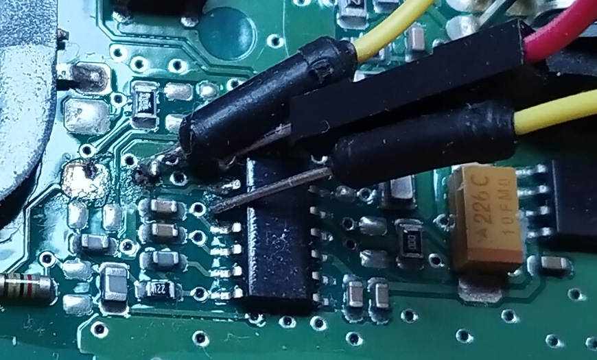
This adapter needs little bit modification. There is no oscillator on the board. There is oscillator pin input but Arduino doesn’t have ability to feed it. So we need to add 4MHz one between PCF7991 pins 6 and 7. Also add 22pF caps between pins and GND. Also remove marked resistor that it is not causing interference to oscillator.
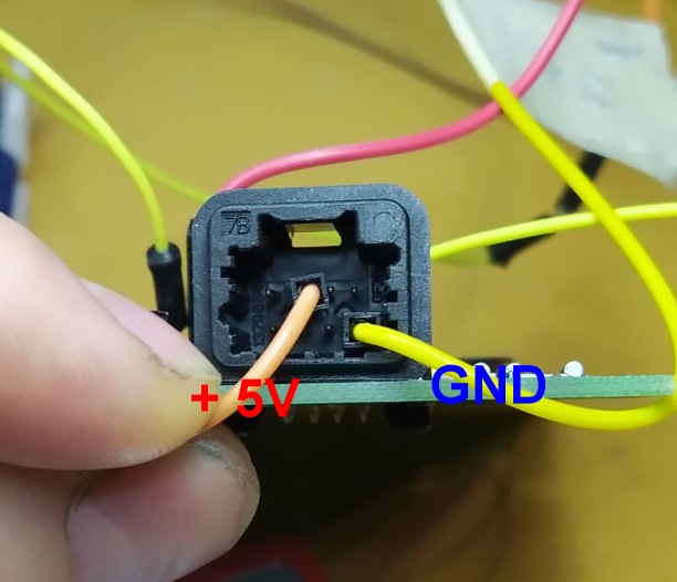
Then there is simpe task left to connect adapter to Arduino. Three data pins, GND and +5V
Tip/further idea: Someone to design Arduino shield that has oscillator and pin routings for interfacing IPROG reader. Or even full Arduino shield with oscillator(s), PCF7991, TMS3705, switching relay, antenna etc!
Hitag2 Key Programmer
New Set ISK feature (set key easily to factory state).
AESHitager app now supports also Hitag2 functionality and development is continued there. Please download at bottom of the page!
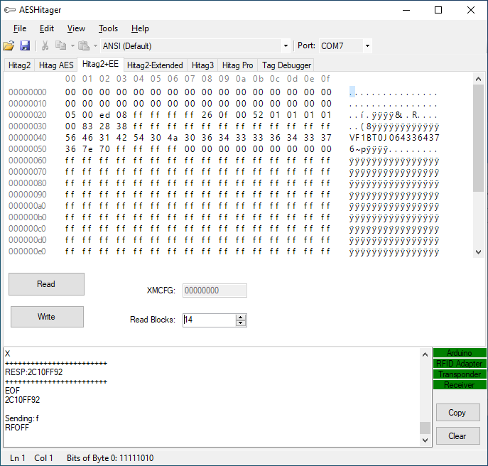
Hitag2+EE
Command set:
Enter XMA state: 00111
INC_BLOCK_POINTER: 00100 + inv
DEC_BLOCK_POINTER: 00101 + inv
READ_PAGE(0-7): 11XXX + inv
WRITE_PAGE(0-7): 10XXX + inv
Now included to main release (scroll down)
Hitag AES Key Programmer (pre-coder)
Cars after 2015 are more common using AES enabled keys. These cards may also need some pre-coding before they can be actually coded to car.
New cards can be access using XMA that is extension for Hitag2. AES cards have however little bit modified command set compared to Hitag2 XMA. Interface information was not public availble anywhere on Internet. Command set was however quite easy to find out using little bit try and error. There wasn’t even need to capture commands from any existing programmer communication. Just give commands to tag using Arduino serial port and see what card respons.
In this project we don’t consider encrypted authentication of keys. There wouldn’t even be much benefit of it because even if it could be possible to read memory segment encrypted there is propably lock bits set that can’t be cleared. And if not segment can be configured to plain and accessed without encryption.
If used key is wanted to use again, there always possibility to clear PCF79xx chip completely and reprogram it using specific in-circuit programmer like VVDI PROG: https://www.xhorsetool.com/wholesale/vvdi-prog-programmer.html
Command set for hitag AES
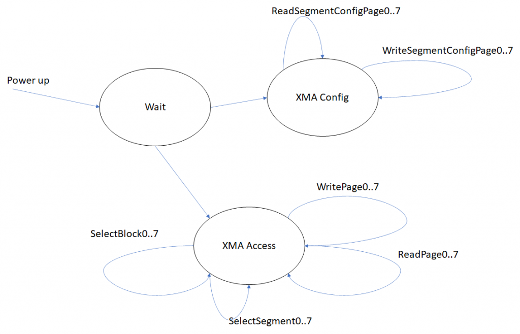
XMA Access State
Enter XMA state: i0540 (01000)
READ_PAGE bit format: 11XXX + inv
READ_PAGE0: i0aC1C0
READ_PAGE1: i0aC980
READ_PAGE2: i0ad140
READ_PAGE3: i0ad900
READ_PAGE4: i0ae0c0
READ_PAGE5: i0ae880
READ_PAGE6: i0af040
READ_PAGE7: i0af800
WRITE_PAGE bit format: 10XXX + inv
WRITE_PAGE0 i0a83c0
WRITE_PAGE1 i0a8B80
WRITE_PAGE2 i0a9340
WRITE_PAGE3 i0a9b00
WRITE_PAGE4 i0aa2c0
WRITE_PAGE5 i0aaa80
WRITE_PAGE6 i0ab240
WRITE_PAGE7 i0aba00
After WRITE_PAGEX command tag returs given command or nothing if page not writable. After that actual data can be written with command i20XXXXXXXX. Tag does not respond anything for that. And data is there!
SELECT_SEGMENT bit format: 00XXX + inv
SELECT_SEGMENT0: i0a07c0
SELECT_SEGMENT1: i0a0f80
SELECT_SEGMENT2: i0a1740
SELECT_SEGMENT3: i0a1f00
SELECT_SEGMENT4: i0a26c0
SELECT_SEGMENT5: i0a2e80
SELECT_SEGMENT6: i0a3640
SELECT_SEGMENT7: i0a3e00
SELECT_BLOCK bit format: 01XXX + inv
SELECT_BLOCK0: i0a45c0
SELECT_BLOCK1: i0a4d80
SELECT_BLOCK2: i0a5540
SELECT_BLOCK3: i0a5d00
SELECT_BLOCK4: i0a64c0
SELECT_BLOCK5: i0a6c80
SELECT_BLOCK6: i0a7440
SELECT_BLOCK7: i0a7c00
XMA Config State
Enter XMA config state: i05e8 (11101)
READ_CONFIG bit format: 01XXX + inv
READ_CONFIG0: i0a45c0
READ_CONFIG1: i0a4d80
READ_CONFIG2: i0a5540
READ_CONFIG3: i0a5d00
READ_CONFIG4: i0a64c0
READ_CONFIG5: i0a6c80
READ_CONFIG6: i0a7440
READ_CONFIG7: i0a7c00
replies are in following format:
0381
8781
8381
0381
0381
8388
8381
8381
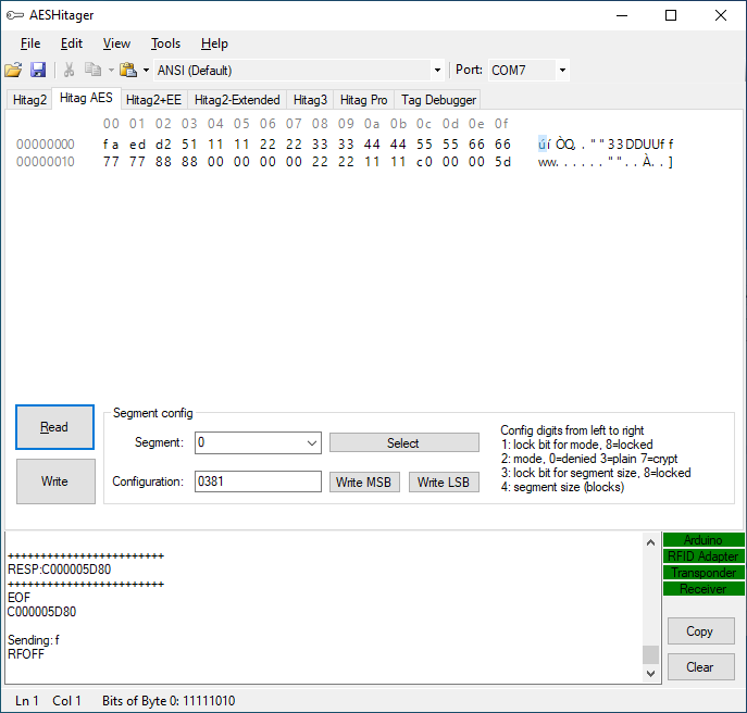
Whrere digits:
1: lock bit for mode
2: mode 0=denied 3=plain 7=crypt
3: lock bit for segment size
4: segment size (blocks)
WRITE_CONFIG_MSB bit format: 10XXX + inv
WRITE_CONFIG_MSB0 i0a83c0
WRITE_CONFIG_MSB1 i0a8B80
WRITE_CONFIG_MSB2 i0a9340
WRITE_CONFIG_MSB3 i0a9b00
WRITE_CONFIG_MSB4 i0aa2c0
WRITE_CONFIG_MSB5 i0aaa80
WRITE_CONFIG_MSB6 i0ab240
WRITE_CONFIG_MSB7 i0aba00
WRITE_CONFIG_LSB bit format: 11XXX + inv
WRITE_CONFIG_LSB0: i0aC1C0
WRITE_CONFIG_LSB1: i0aC980
WRITE_CONFIG_LSB2: i0ad140
WRITE_CONFIG_LSB3: i0ad900
WRITE_CONFIG_LSB4: i0ae0c0
WRITE_CONFIG_LSB5: i0ae880
WRITE_CONFIG_LSB6: i0af040
WRITE_CONFIG_LSB7: i0af800
After WRITE_CONFIGX command tag returs given command or nothing if page not writable. After that mode data MSB(lock bit and mode) or LSB(lock bit and size) can be written with command (one byte) i08XX. Tag does not respond anything for that.
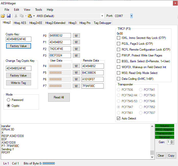
Windows Application
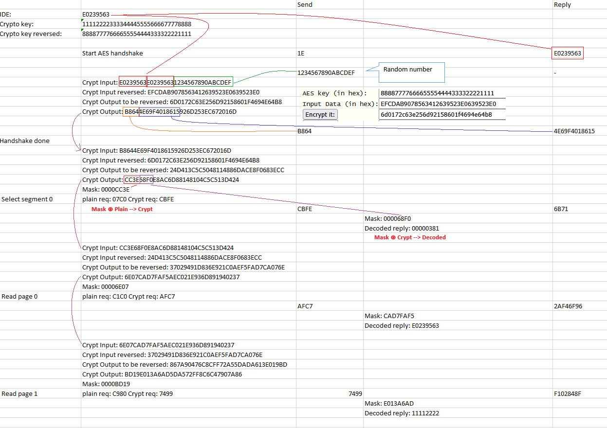
Segment 0 is storing all relevant information for authentication. Key ID is located at 32 first bits (E0 23 95 63). After that there is factory default 128 bit crypto key (11 11 22 22 33 33 44 44 55 66 66 77 77 88 88)
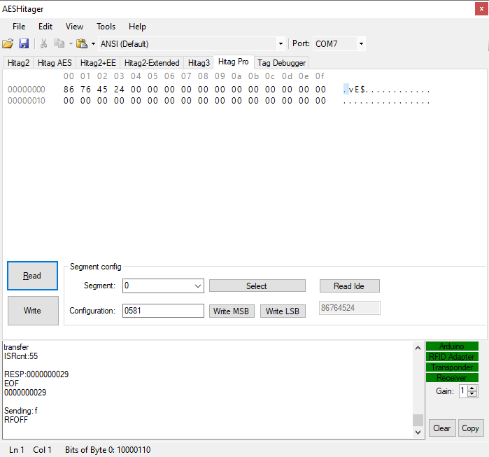
Hitag Pro
Command set:
Read IDE: 0011
Plain authenticate XMA: 0000 0000 XXXX… Where XXXX is IDE read from the card(32bit)
Segment configuration: 1111 1111 XXXX… Where XXXX is IDE read from the card(32bit)
Select Segment/block: 1101 1AAA BBBB Where AAA is segment and BBBB block
Read page: 0000 0AAA Where AAA is page address
Write page: 1000 0AAA XXXX… YY.. Where AAA is page address and XXXX data to be written (32bit), YY = CRC8(8bit)
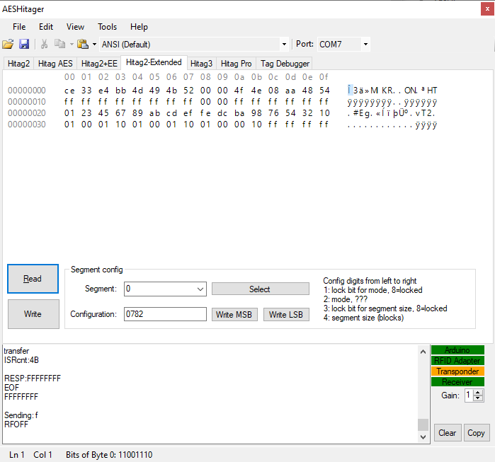
Hitag2 Extended
Command set:
Very similar to AES but with minor differences:
Enter XMA state: 00000
READ_PAGE bit format: 11XXX + inv
WRITE_PAGE bit format: 10XXX + inv
SELECT_SEGMENT bit format: 00XXX + inv
Enter XMA config state: 10100
READ_CONFIG bit format: 01XXX + inv
WRITE_CONFIG_MSB bit format: 10XXX + inv
WRITE_CONFIG_LSB bit format: 11XXX + inv
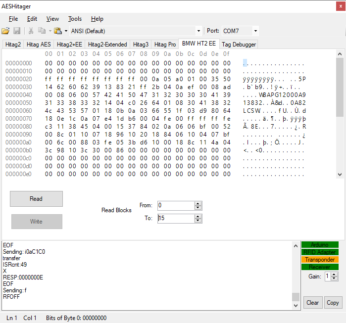
Hitag2 BMW EE
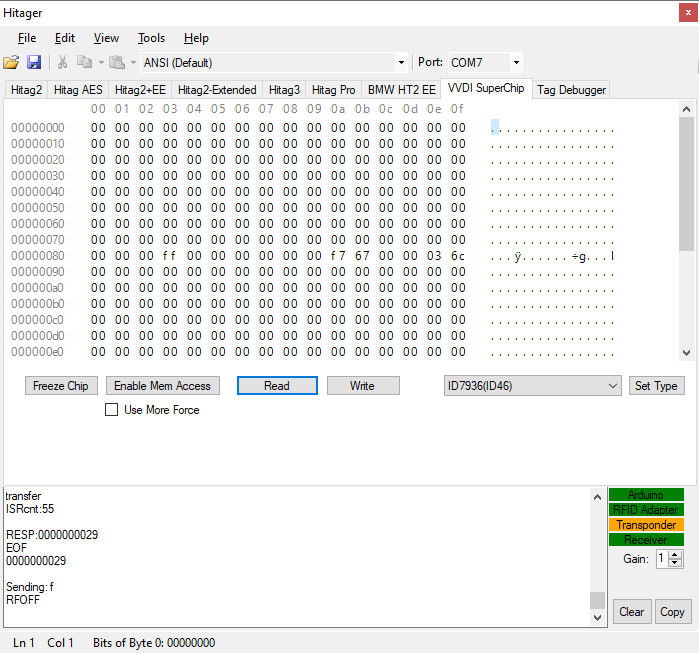
VVDI SuperChip, XT27A
Hitag AES Encrypted Mode
Got some crucial help from one friend for AES encrypted protocol. So, here it is implemented.
Communication is established with secure handshaking. After that Hitag AES transponder goes directly to XMA mode. So, it is not possible to change segment configuration in that mode. Segment configuration is always done in plain mode.
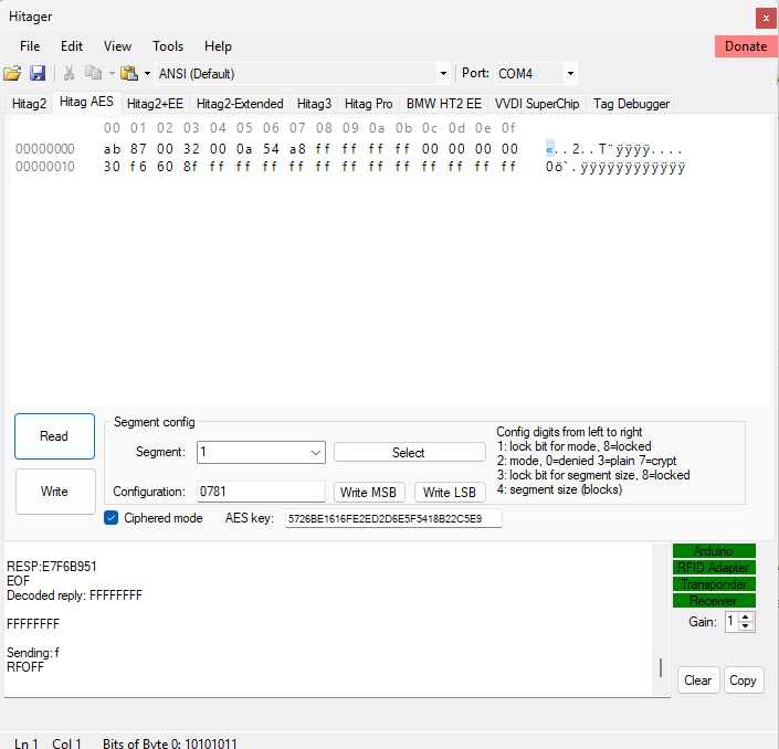
Ciphered mode offers possibility to check and modify segments that are encrypted and locked.
Hitag AES encrypted protocol
Handshaking is done by sending random data (challenge) to transponder. Random number with IDE is used as seed for crypt data. Both sides do the same AES calculation. Next step ABIC sends 16 bit of crypt data to transponder. If that match for transponder calculation, transponder replies next 48 bit of crypt data. ABIC side then verifies data and hadshaking done.
Next steps are always based on crypting again full output of earlier step crypt data. New data is then used as mask and crypted message is formed with XOR operation with necessary amount of bits.
Data is not ever decrypted with AES algorithm. XORing algorithm is always used both sides.
You may test AES encryption with online tool like this: https://testprotect.com/appendix/AEScalc
Visual Studio has crypto class RijndaelManaged that can be used to encrypt messages with mode CipherMode.ECB
Application
User can select encrypted protocol by checking check box and giving AES crypto key. AES protocol is high energy consuming. Transponder needs to be carefully located on transmitter coil to tranfer all needed energy.
Hitager AES crypto mode application package (Windows binary only):
https://kivijakola.fi/share/hitager/hitager_aes_crypto.zip
Source code
https://kivijakola.fi/share/hitager/sources_aes_crypt.zip
Videos
Example of AES key programming with Renault ECU Tool programmer to precode cards: http://www.immo-tools.lt/site/files/failai/X98_AllCardsLost.pdf Yes! you can do the same with this open source projet!
Source codes available at GitHub: https://github.com/kivijakola/hitager
One Reply to “Hitag2 and AES Open Source Key Programmer”