How to get broken heatpump fixed and running with replaced electronic.
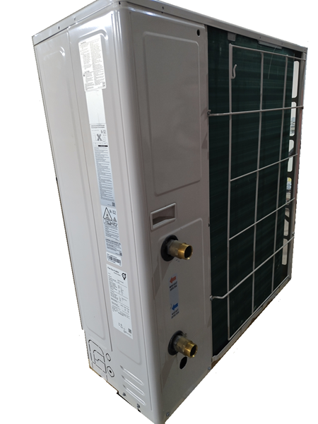
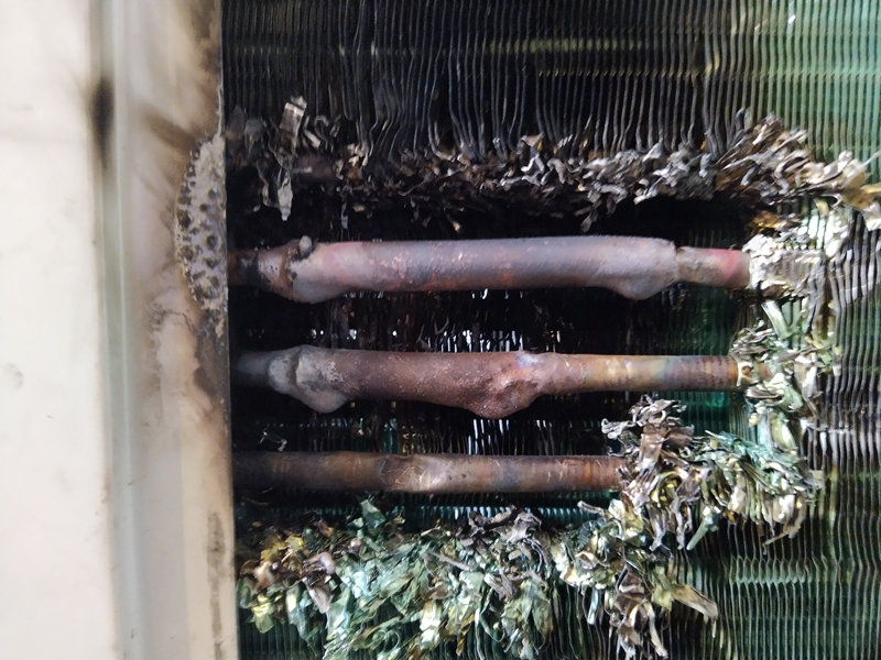
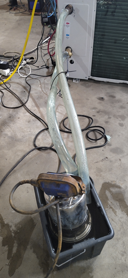
Got Samsung ae080rxydgg 8kW inverter air to water heatpump outdoor unit. There was holes in heat transfer pipes that had to be repaired first
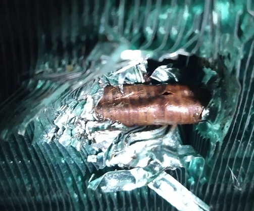
Pipes have very thin wall and difficult to weld
After repairing, leak testing, vacuuming and filling R32 tried to get compressor starting with pump own controller. it turned out to be impossible without indoor unit. Next step was to try cheap Chinese variable frequency drive.
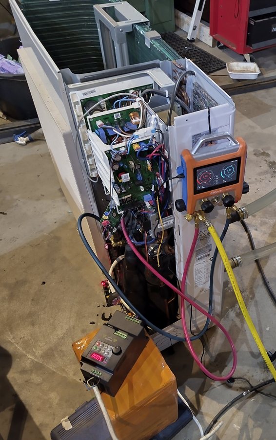
Bad luck! This VFD didn’t understand anything about BLDC motors. It was only able to speed up around 10Hz and then going to fail state because of over current.
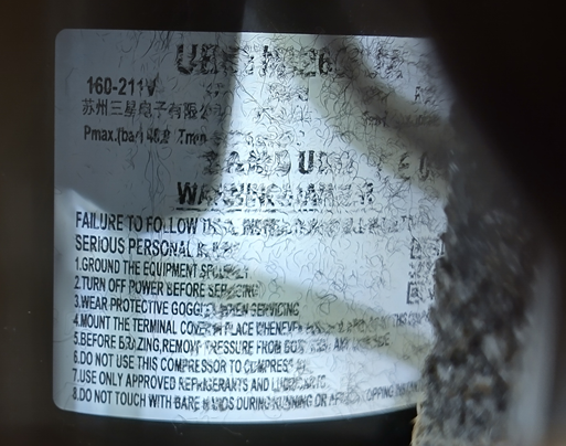
Compressor type was BLDC Twin Rotary UB8TN8265FJWSG. There was not very much information available about it.
Next try with Optidrive VFD. Those have well documented BLDC option.
Following parameters were used:
P-07 kE = 160V
P-08 IN = 9 A
P-09 fN = 200Hz
P-14 = 201
P-51 motor type = 3 (BLDC)
P-52 Auto tune = 1
Optimal kE value was searched using minimum magnetising current pinciple presented in Tip & Tricks chapter.
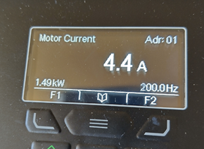
Compressor was smoothly ticking to 200 Hz after parameter setup!
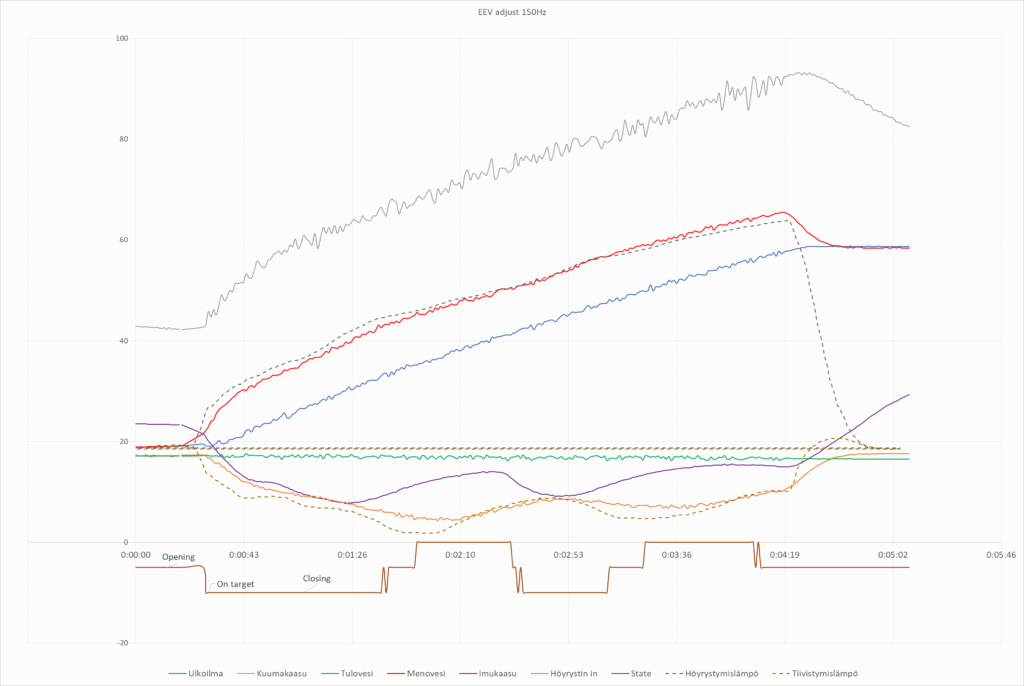
First test without automatic EEV valve control
This was quite bad result indeed but the compressor was working! Evaporation temperature was pretty soon exeeding outdoor temperature and energy was transfered to air instead of taking energy from it. Warming energy was coming from compressor used electricity.
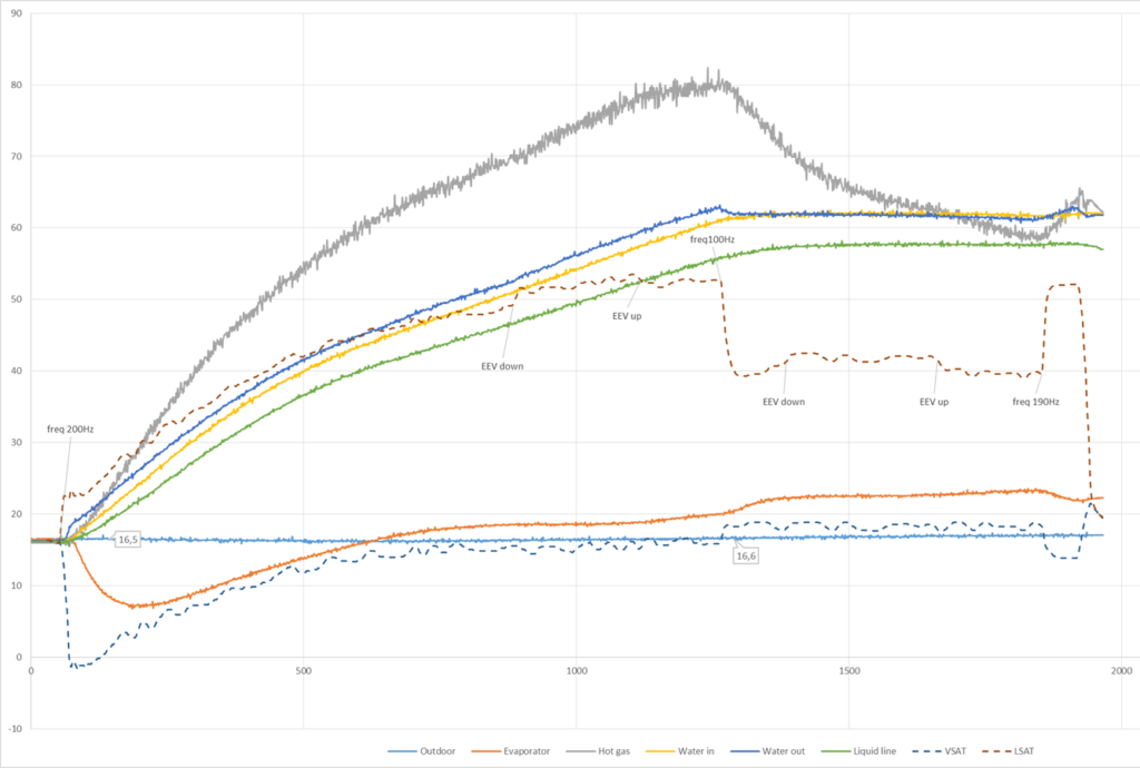
Added temperature based EEV adjstment. Target is to keep evaporator input/output temperature difference within 4..6 degrees. Temperature sensors were moved to better places to get more precise temperature reference values. Original setup was using some different algorithm as there was not any sensor at input nor output. Instead middle of evaportator. Probably that was used with outdoor temperature for warming and cooling.
Temperature adjustment was quite difficult with tiny warming water capasity. There is quite big delay before temperature sensors react to adjustment and temperature difference started oscillating.
Oscillation can be avoided at pool warming just slowing adjustment as environment does not change rapidly.
Control Electronics
Temperature Sensors
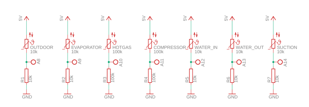
There is 7 NTC temperature sensors in the unit.
8 pin connector:
1: Outdoor 10k NTC
2: Evaporator 10k NTC (moved to evaporator input)
3: Hot gas 100k NTC
4: Compressor 100k NTC
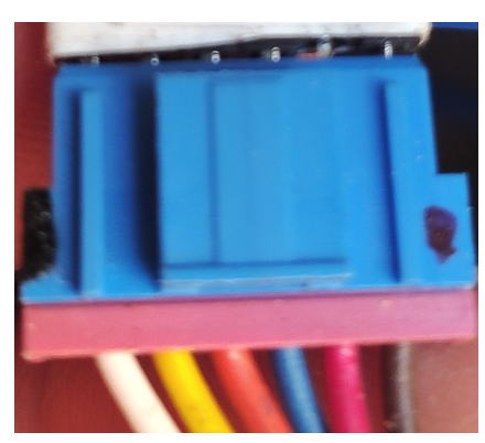
4 pin connector:
1: Water in 10k NTC
2: Water in 10k NTC
2 pin connector
Liquid line 10k NTC (moved to suction line)
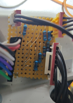
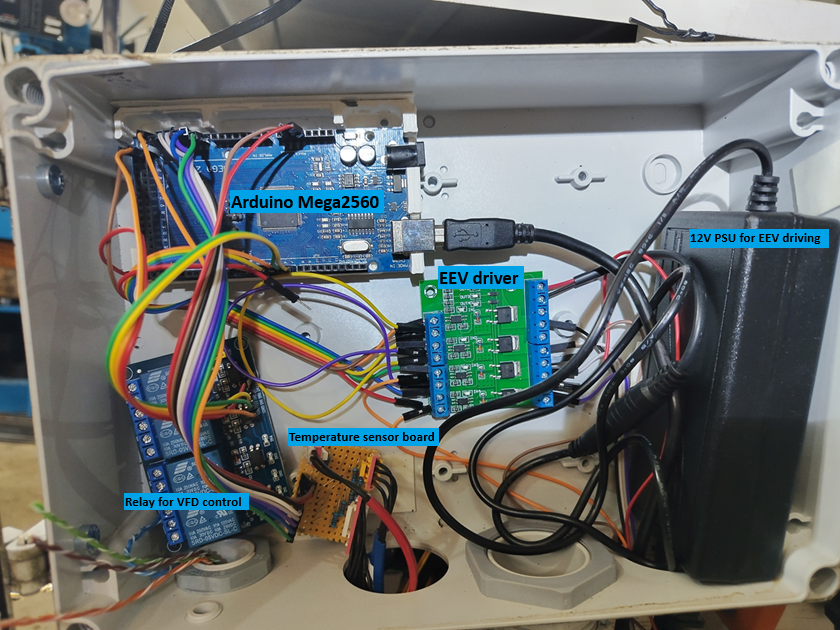
Sensors are connected to bread board using voltage division principle using same label value resistor pair as NTC has. Voltage division outputs were connected to Arduino analog input pins 8..14 because some lower pins had interferencing resistance.
EEV Controller
There is SXK-19 electronic expansion valve in the system. This can be controlled like 4 winding stepper motor. Some driver board is needed between motor and Arduino. Found some ”MOS FET F5305S 4 Channels Pulse Trigger Switch Controller” from Aliexpress.
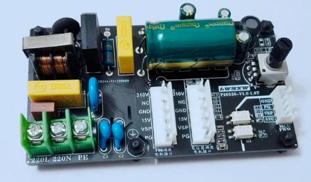
Fan Motor Controller
Fan has also DC rated motor. Model FMDC531SSA, 310V, 0.48A, 900r/min. This can be easily driven at static speed using ”310V DC Brushless Five-wire Internal Machine DC Fan Motor Drive Board” controller ordered from Aliexpress. Basic operation for this motor is to feed voltage from 230V bridge rectifier and also smaller (15V) control voltage.
Motor cable connector can be directly attached on second connector on board. Speed can be adjusted with potentiometer. Full speed was set to get full power for pool warming.
Arduino can be set also to feed speed control signal to pin header for some other use cases.
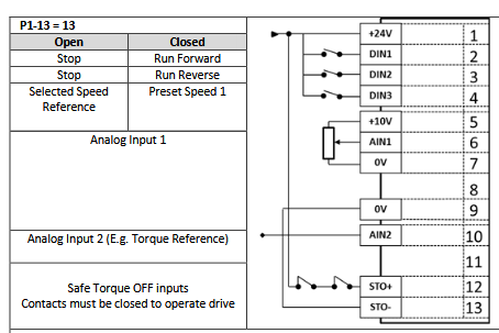
Inverter control
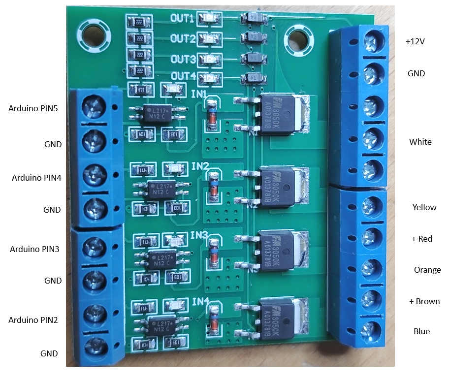
Relay board is used between Arduino and inverter to control compressor ON/OFF

Heatpump overpressure pressostat is connected between inverter pins 1 and 12. This is safety function to protect compressor at ultimate fail cases. If, for example, water pump and temperature sensor fails, condencer temperature and pressure rise uncontrollable. Compressor will burn if not stopped in time.
Overpressure pressostat opens at 48 bar, stops compressor and prevents any damage. Inverter reset is needed before compressor will start again.
It could be also possible to automatically control compressor frequency with analag signal 0-10V connected to pin 6. However, pool warming can be just done with static setting near full speed.
Arduino Source Code
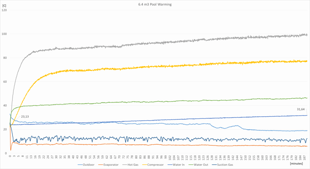
Pool Warming
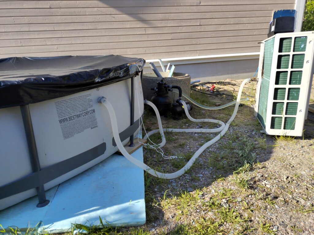
System was installed to warm 6.4m3 swimming pool. Here is example of warming process temperatures. Starting temperature was 23C and after three hours temperature was 31C.
System is not closed there is lot of heat escaping all the time to the air. So, efficiency seems to be quite great. Warming 6.4m3 water 8 degrees requires around 60kWh energy. So, 20kW for 3 hours. Compressor was taking around 1.8kW when running.
Basically efficiency cannot be this great. This can be explained just that water in the pool is not fully homogeneusly mixed. But still output power can be over 10kW as manufacturer 8kW power is rated at lower outdoor tempreatures.